Here is the schematic for the Yamaha Breath Controller to MIDI converter.
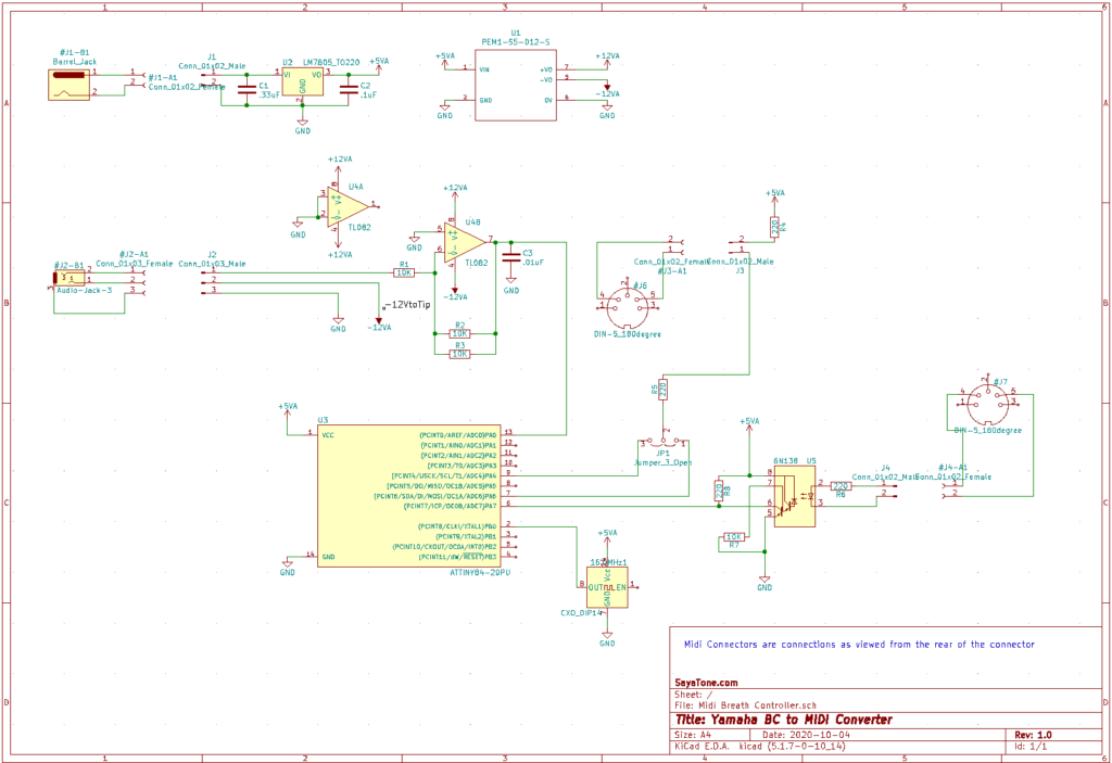
The design is simple. Starting with the power section. It is not the most efficient but is designed around parts that I had available. The main power is based on a 7805 linear voltage regulator (U2) and a external DC supply like a wall-wart. Since the 7805 requires an input supply voltage to be greater than 8V, it can be powered by a wall-wart of 9V or more. A 12V wall-wart can also be used but will generate a bit of heat. The second part of the power supply is a DC-DC converter PEME1-S5-D12-S (U1) that converts the regulated 5V supply and generates 2 additional voltage rails +/- 12V. The DC-DC converter can supply a max current of 42mA which is more than enough for the breathcontroller which draws about 12mA as well as the opamp. A USB 5V supply could be used in place of the 7805 regulator as the current requirement of the circuit is well under 500mA. I personally dislike working with the USB connectors as it’s hard to drill rectangular USB socket holes in project cases and I have a handful of wall warts and round power jacks.
The BreathController (based on Yamaha DX7 schematics) uses a negative supply voltage and returns a negative voltage between 0V and the supply based on the amount of breath pressure through the BC. Using a -12V supply, I measured the output voltages of the BC1 and BC2 that I own. The BC1 range is (-0.26V ~ -10V) and the BC2 range is (-0.14V ~ -10V) . Using a TL-082 op-amp (U4) in an inverting configuration with a gain of -0.5 results in a converted output voltage of 0.13 – 5V and 0.07 – 5 V respectively which is conveniently within the ADC voltage specs of the ATTINY microcontroller. The reason why I used 2 – 10K resistors ( R2 / R3 ) in parallel instead of a 5K resistor is because, 5K resistors are not usually available and 10K resistors are cheap and I have a bunch. Additionally, 2 – 10K resistors in parallel is closer to 5K than a nominal 4.7K resistor.
For the microcontroller, I used the ATTINY84 because that’s what I had around. The ATTINY84 has an internal clock but I had a hard time getting the MIDI output to match the exact 31.25K baud rate without using an external clock. So, again, since I had a 16mhz oscillator, that’s what I used. So when you program your ATTINY, make sure not to forget to blow the fuses correctly.
The schematic does have an MIDI input section with a 6N138 optoisolator (U5) but if you want to just convert the breath controller input to MIDI data, then you can leave out that part completely. I wanted to merge MIDI input with the breath controller MIDI output but since the Arduino serial library do not allow simultaneous read/writes, I had a lot of difficulties getting the merge to work even using some of the 3rd party serial libraries like SoftwareSerial. Also, SoftwareSerial uses the timer which means that PA4 (pin9) cannot be used for the MIDI output which is what the ATTINY serial library uses for the serial output. The Jumper (JP1) allows me to switch between the MIDI output only software which relies on the Arduino Serial library and transmits on pin 9 vs the SoftwareSerial library which I programmed to transmit on pin 6. Again, if you just need to transmit MIDI out data, you can tie the MIDI output directly to pin 9 and forgo the jumper. I did not put a 5V buffer between the microcontroller output and MIDI connector as I found the ATTINY had enough current to drive the current loop.
The software is very simple for the BC -> MIDI out conversion. As I mentioned, getting the MIDI IN merge was tricky and is not without bugs. I won’t post it until it gets a bit more stable.
So the code below is strictly to deal with breath controller to MIDI conversion only. The ADC on the ATTINY is a 10 bit converter (0-1023) so to convert it to an 8 bit value (0-255), which is needed by MIDI, I divided by 8. Be warned, this code may flood your MIDI stream with data especially with a clock as high as 16mhz. I added a comparison of the previous value so the microcontroller would only send a message if there was a change in BC voltage. It helps but this software tends to send quite a bit of MIDI data.
void setup() {
  Serial.begin( 31250, SERIAL_8N1 );  // this uses pin 9 to write
}

void loop() {
  int val = analogRead(0) / 8;   // read pin 13 on ATTINY
  int val2 = 0;
  while ( 1 ) {
    val2 = analogRead(0) / 8 ;
    if ( val2 != val ) {
      Serial.write(0xB0);   // continuous controller
      Serial.write(0x02);   // breath controller
      Serial.write(val2);
      val = val2;
    }
  }
}